Tubewell Steel & Engg. Co. is a leading manufacturer and stockist specializing in Alloy Steel Pipes, Tubes, Fittings and Flanges for critical industrial applications.
Solid ASTM A182 chrome-moly blind flanges for closing pipe ends, vessel nozzles and test points in high-temperature, high-pressure systems.
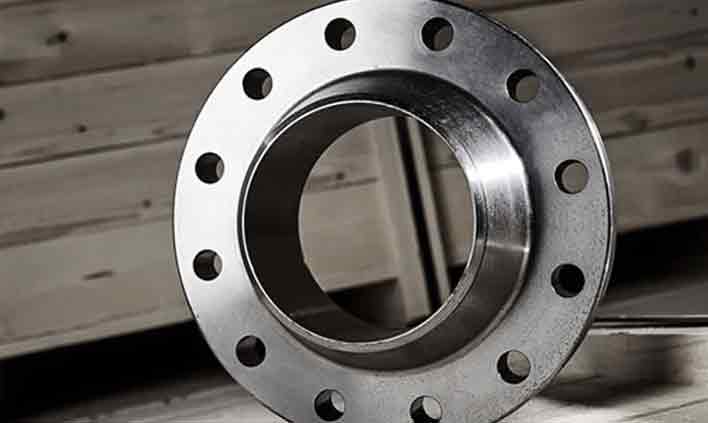
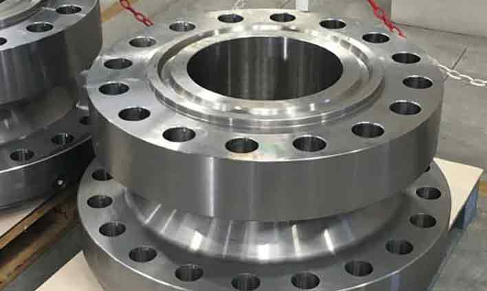
Tubewell Steel & Engg. Co. manufactures, stocks and supplies alloy steel blind flanges from Mumbai, India in ASTM A182 F5, F9, F11, F22 and F91. A blind flange is a solid, unbored disc that bolts to a mating flange to seal the end of a pipe, valve or vessel nozzle – allowing lines to be isolated, pressure tested or extended later without cutting.
Reliable isolation and closure for chrome-moly piping systems
A blind flange has the same outside diameter, bolt circle and facing as the other flanges of its class, but no bore. Bolted against a weld neck, slip-on or other mating flange with a suitable gasket, it seals the line completely. Because the full system pressure acts across the whole face, blind flanges are among the most highly stressed flange types – especially in larger sizes – which is why material grade, heat treatment and thickness must be correct for the design temperature.
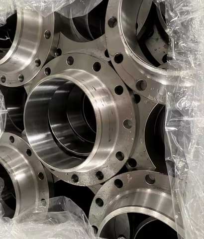
We forge alloy steel blind flanges in ASTM A182 F5, F9, F11, F22 and F91, heat treat them as required and machine them to ASME B16.5, B16.47, MSS SP-44 or EN 1092-1 (Type 05). Raised face, flat face and RTJ facings are available, and blinds can be drilled and tapped for vents, drains or instrument connections, or supplied with lifting lugs. Every piece is PMI-checked, hardness tested and supplied with EN 10204 3.1 / 3.2 certificates.
Standard supply range for alloy steel blind flanges
| Parameter | Details |
|---|---|
| Material Standard | ASTM A182, ASME SA182 |
| Grades | F5, F5a, F9, F11 Class 1 / 2 / 3, F12, F22 Class 1 / 3, F91 |
| Dimension Standard | ASME B16.5 (1/2" – 24"), ASME B16.47 Series A & B (26" – 48"), MSS SP-44, EN 1092-1 Type 05, ASME B16.48 |
| Size | 1/2" NB to 48" NB (DN 15 – DN 1200) |
| Pressure Class | ASME Class 150, 300, 600, 900, 1500, 2500 |
| PN Rating | PN6, PN10, PN16, PN25, PN40, PN64 |
| Types | Blind (BL), Spectacle Blind, Spacer & Paddle Blank, Tapped Blind, Reducing Blind |
| Facing | Raised Face (BLRF), Flat Face (BLFF), Ring Type Joint (BL-RTJ), Tongue & Groove |
| Face Finish | Serrated 125 – 250 µin Ra (3.2 – 6.3 µm); RTJ groove 63 µin Ra max |
| Manufacturing | Forged disc / rolled ring, CNC machined |
| Heat Treatment | Annealed or Normalized & Tempered per ASTM A182 (F91: N&T) |
| Options | Drilled & tapped vent / drain, lifting lugs, jack-screw holes |
| Testing | PMI, Hardness, Tensile, Impact, UT, MPI / DPT, Visual & Dimensional |
| Certificates | EN 10204 3.1 / 3.2, IBR Certification, NACE MR0175, TPI Reports |
Grades available for blind flanges and their international equivalents
| Grade | ASTM / ASME | UNS | EN 10222-2 | W.Nr. | JIS G3203 | Nominal |
|---|---|---|---|---|---|---|
| F5 | A182 F5 | K41545 | X16CrMo5-1 | 1.7366 | SFVAF5B | 5Cr-0.5Mo |
| F9 | A182 F9 | K90941 | X11CrMo9-1 | 1.7386 | SFVAF9 | 9Cr-1Mo |
| F11 | A182 F11 Cl.2 | K11572 | 13CrMo4-5 | 1.7335 | SFVAF11A | 1.25Cr-0.5Mo |
| F22 | A182 F22 Cl.3 | K21590 | 11CrMo9-10 | 1.7383 | SFVAF22B | 2.25Cr-1Mo |
| F91 | A182 F91 | K90901 | X10CrMoVNb9-1 | 1.4903 | SFVAF28 | 9Cr-1Mo-V |
Equivalents are the nearest comparable grades for reference; confirm suitability against the governing design code before substitution.
Weight %, as per ASTM A182
| Grade | C | Mn | P max | S max | Si | Cr | Mo | Others |
|---|---|---|---|---|---|---|---|---|
| F5 | 0.15 max | 0.30 – 0.60 | 0.030 | 0.030 | 0.50 max | 4.0 – 6.0 | 0.44 – 0.65 | Ni 0.50 max |
| F9 | 0.15 max | 0.30 – 0.60 | 0.030 | 0.030 | 0.50 – 1.00 | 8.0 – 10.0 | 0.90 – 1.10 | – |
| F11 Cl.2 | 0.10 – 0.20 | 0.30 – 0.80 | 0.040 | 0.040 | 0.50 – 1.00 | 1.00 – 1.50 | 0.44 – 0.65 | – |
| F22 Cl.3 | 0.05 – 0.15 | 0.30 – 0.60 | 0.040 | 0.040 | 0.50 max | 2.00 – 2.50 | 0.87 – 1.13 | – |
| F91 | 0.08 – 0.12 | 0.30 – 0.60 | 0.020 | 0.010 | 0.20 – 0.50 | 8.0 – 9.5 | 0.85 – 1.05 | V 0.18–0.25, Nb 0.06–0.10, N 0.03–0.07, Ni 0.40 max |
Minimum values at room temperature, as per ASTM A182
| Grade | Tensile Strength | Yield Strength (0.2%) | Elongation (in 2") | Reduction of Area | Hardness (HBW) |
|---|---|---|---|---|---|
| F5 | 485 MPa (70 ksi) min | 275 MPa (40 ksi) min | 20% min | 35% min | 143 – 217 |
| F9 | 585 MPa (85 ksi) min | 380 MPa (55 ksi) min | 20% min | 40% min | 179 – 217 |
| F11 Cl.2 | 485 MPa (70 ksi) min | 275 MPa (40 ksi) min | 20% min | 30% min | 143 – 207 |
| F22 Cl.3 | 515 MPa (75 ksi) min | 310 MPa (45 ksi) min | 20% min | 30% min | 156 – 207 |
| F91 | 620 MPa (90 ksi) min | 415 MPa (60 ksi) min | 20% min | 40% min | 248 max |
Typical values (for reference)
| Property | F5 | F9 | F11 | F22 | F91 |
|---|---|---|---|---|---|
| Density (g/cm³) | 7.75 | 7.70 | 7.75 | 7.80 | 7.76 |
| Modulus of Elasticity (GPa) | 210 | 213 | 205 | 210 | 218 |
| Thermal Conductivity at 100°C (W/m·K) | 33 | 26 | 37 | 36 | 26 |
| Mean Thermal Expansion 20–300°C (µm/m·°C) | 11.9 | 11.6 | 12.4 | 12.6 | 11.3 |
| Specific Heat (J/g·°C) | 0.46 | 0.46 | 0.46 | 0.46 | 0.45 |
| Approx. Max. Service Temp. (°C) | ≈ 650 | ≈ 650 | ≈ 595 | ≈ 600 | ≈ 650 |
ASME B16.5 Class 150 & Class 300 blind flanges – dimensions in mm, weight in kg
| NPS | Cl.150 OD | Cl.150 Thk | Cl.150 Bolts | Cl.150 Approx. Wt | Cl.300 OD | Cl.300 Thk | Cl.300 Bolts | Cl.300 Approx. Wt |
|---|---|---|---|---|---|---|---|---|
| 1/2" | 90 | 9.6 | 4 × 1/2" | 0.4 | 95 | 12.7 | 4 × 1/2" | 0.6 |
| 3/4" | 100 | 11.2 | 4 × 1/2" | 0.7 | 115 | 14.3 | 4 × 5/8" | 1.1 |
| 1" | 110 | 12.7 | 4 × 1/2" | 0.9 | 125 | 15.9 | 4 × 5/8" | 1.4 |
| 1 1/4" | 115 | 14.3 | 4 × 1/2" | 1.1 | 135 | 17.5 | 4 × 5/8" | 1.9 |
| 1 1/2" | 125 | 15.9 | 4 × 1/2" | 1.5 | 155 | 19.1 | 4 × 3/4" | 2.7 |
| 2" | 150 | 17.5 | 4 × 5/8" | 2.4 | 165 | 20.7 | 8 × 5/8" | 3.2 |
| 2 1/2" | 180 | 20.7 | 4 × 5/8" | 4.1 | 190 | 23.9 | 8 × 3/4" | 4.9 |
| 3" | 190 | 22.3 | 4 × 5/8" | 5.0 | 210 | 27.0 | 8 × 3/4" | 6.9 |
| 4" | 230 | 22.3 | 8 × 5/8" | 7.2 | 255 | 30.2 | 8 × 3/4" | 11.7 |
| 5" | 255 | 22.3 | 8 × 3/4" | 8.8 | 280 | 33.4 | 8 × 3/4" | 15.7 |
| 6" | 280 | 23.9 | 8 × 3/4" | 11.5 | 320 | 35.0 | 12 × 3/4" | 21.4 |
| 8" | 345 | 27.0 | 8 × 3/4" | 20.0 | 380 | 39.7 | 12 × 7/8" | 34.4 |
| 10" | 405 | 28.6 | 12 × 7/8" | 28.9 | 445 | 46.1 | 16 × 1" | 53.9 |
| 12" | 485 | 30.2 | 12 × 7/8" | 44.2 | 520 | 49.3 | 16 × 1 1/8" | 79.1 |
| 14" | 535 | 33.4 | 12 × 1" | 59.1 | 585 | 52.4 | 20 × 1 1/8" | 106.1 |
| 16" | 595 | 35.0 | 16 × 1" | 76.3 | 650 | 55.6 | 20 × 1 1/4" | 139.1 |
| 18" | 635 | 38.1 | 16 × 1 1/8" | 94.4 | 710 | 58.8 | 24 × 1 1/4" | 175.5 |
| 20" | 700 | 41.3 | 20 × 1 1/8" | 123.8 | 775 | 62.0 | 24 × 1 1/4" | 222.5 |
| 24" | 815 | 46.1 | 20 × 1 1/4" | 187.7 | 915 | 68.3 | 24 × 1 1/2" | 341.4 |
Thk = minimum blind flange thickness excluding 2 mm (0.06") raised face. Bolts = No. × Bolt Diameter. Approximate weights are calculated for raised-face blinds at 7.85 g/cm³ and are for reference only; actual weights vary with grade and machining.
Where alloy steel blind flanges are used
End closures on steam headers and turbine bypass lines.
Isolation of heater and reactor piping during shutdowns.
Temporary closures for pressure testing of new piping.
Manway and inspection nozzle covers on reactors and drums.
Future tie-in points and dead-legs in process units.
Header end caps and inspection openings on boilers.
Quality you can verify on every heat
Large inventory for fast dispatch
MTC EN 10204 3.1 / 3.2
Positive material identification
Pan-India & export shipping
Quick answers about alloy steel blind flanges
Get competitive pricing, ready stock and complete documentation.