Tubewell Steel & Engg. Co. is a leading manufacturer and stockist specializing in Alloy Steel Pipes, Tubes, Fittings and Flanges for critical industrial applications.
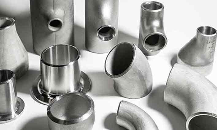
ASTM A234 chrome-moly concentric and eccentric buttweld reducers for smooth line-size transitions in high-temperature steam and process piping.
Tubewell Steel & Engg. Co. manufactures, stocks and supplies alloy steel reducers from Mumbai, India in ASTM A234 WP5, WP9, WP11, WP22 and WP91. Our seamless and welded concentric and eccentric reducers join pipes of different sizes with a smooth conical transition that minimises turbulence and stress concentration.
Smooth size transitions for chrome-moly piping
Alloy steel buttweld reducers connect two pipes of different nominal sizes in chrome-moly piping systems. A concentric reducer has the large and small ends on a common centerline and is used in vertical lines and where flow symmetry matters. An eccentric reducer has one flat side – installed flat-side-up on pump suction lines to prevent air pockets, or flat-side-down on pipe racks to keep a constant bottom of pipe for drainage and support.
Our reducers are formed from seamless A335 pipe by hot or cold swaging, or from plate for larger welded sizes, and then heat treated as required by ASTM A234 for the selected grade. End-to-end lengths conform to ASME B16.9, both ends are bevelled per ASME B16.25 with wall thickness matched to the respective pipe schedules, and every lot carries EN 10204 3.1 certificates with IBR and TPI available on request.
Standard supply range for alloy steel buttweld reducers
| Parameter | Details |
|---|---|
| Standard | ASTM A234, ASME SA234 |
| Grades | WP5, WP9, WP11 (Cl.1/2/3), WP22 (Cl.1/3), WP91 |
| Dimension Standard | ASME B16.9, MSS SP-43 |
| Size (NB) | Seamless: 3/4" × 1/2" to 24" × 20"; Welded: up to 48" NB |
| Wall Thickness | SCH 10, 20, 40, STD, 60, 80, XS, 100, 120, 140, 160, XXS |
| Reducer Types | Concentric Reducer, Eccentric Reducer |
| Related Types | Reducing Tee, Reducing Elbow, Swage Nipple (forged) |
| Schedule Combination | Same or different schedules on large and small ends |
| Manufacturing | Seamless (WP) – hot / cold swaged; Welded (WPW) from plate |
| Heat Treatment | Annealed or Normalized & Tempered; WP91: N 1040–1080°C + T 730–800°C |
| Ends | Bevelled Ends as per ASME B16.25 |
| Marking | As per MSS SP-25 – grade, size, schedule, heat no. |
| Testing | RT (welded), UT, MPI / DPT, Hardness, PMI, Dimensional |
| Certificates | EN 10204 3.1 / 3.2, IBR, NACE MR0175, TPI Reports |
Grades available for alloy steel reducers
| Grade | ASTM / ASME | UNS | EN | W.Nr. | JIS | Matching Pipe / Forging |
|---|---|---|---|---|---|---|
| WP5 | A234 / SA234 WP5 | K41545 | X11CrMo5 | 1.7362 | STPA 25 | A335 P5 / A182 F5 |
| WP9 | A234 / SA234 WP9 | K90941 | X11CrMo9-1 | 1.7386 | STPA 26 | A335 P9 / A182 F9 |
| WP11 | A234 / SA234 WP11 | K11597 | 13CrMo4-5 | 1.7335 | STPA 23 | A335 P11 / A182 F11 |
| WP22 | A234 / SA234 WP22 | K21590 | 10CrMo9-10 | 1.7380 | STPA 24 | A335 P22 / A182 F22 |
| WP91 | A234 / SA234 WP91 | K90901 | X10CrMoVNb9-1 | 1.4903 | STPA 28 | A335 P91 / A182 F91 |
Weight %, as per ASTM A234
| Grade | C | Mn | P | S | Si | Cr | Mo | Others |
|---|---|---|---|---|---|---|---|---|
| WP5 | 0.15 max | 0.30 – 0.60 | 0.040 max | 0.030 max | 0.50 max | 4.0 – 6.0 | 0.44 – 0.65 | – |
| WP9 | 0.15 max | 0.30 – 0.60 | 0.030 max | 0.030 max | 1.00 max | 8.0 – 10.0 | 0.90 – 1.10 | – |
| WP11 Cl.1 | 0.05 – 0.15 | 0.30 – 0.60 | 0.030 max | 0.030 max | 0.50 – 1.00 | 1.00 – 1.50 | 0.44 – 0.65 | – |
| WP11 Cl.2 / Cl.3 | 0.05 – 0.20 | 0.30 – 0.80 | 0.040 max | 0.040 max | 0.50 – 1.00 | 1.00 – 1.50 | 0.44 – 0.65 | – |
| WP22 Cl.1 / Cl.3 | 0.05 – 0.15 | 0.30 – 0.60 | 0.040 max | 0.040 max | 0.50 max | 1.90 – 2.60 | 0.87 – 1.13 | – |
| WP91 | 0.08 – 0.12 | 0.30 – 0.60 | 0.020 max | 0.010 max | 0.20 – 0.50 | 8.0 – 9.5 | 0.85 – 1.05 | Ni 0.40 max, V 0.18–0.25, Nb 0.06–0.10, N 0.03–0.07, Al 0.02 max |
Values at room temperature as per ASTM A234
| Grade | Tensile Strength | Yield Strength (min) | Elongation (Long.) | Elongation (Trans.) | Hardness (max) |
|---|---|---|---|---|---|
| WP5 Cl.1 / WP9 Cl.1 | 415 – 585 MPa (60 – 85 ksi) | 205 MPa (30 ksi) | 30% | 20% | 217 HB |
| WP5 Cl.3 / WP9 Cl.3 | 485 – 655 MPa (70 – 95 ksi) | 275 MPa (40 ksi) | 22% | 14% | 217 HB |
| WP11 Cl.1 | 415 – 585 MPa (60 – 85 ksi) | 205 MPa (30 ksi) | 30% | 20% | 197 HB |
| WP11 Cl.2 | 485 – 655 MPa (70 – 95 ksi) | 275 MPa (40 ksi) | 22% | 14% | 197 HB |
| WP11 Cl.3 | 520 – 690 MPa (75 – 100 ksi) | 310 MPa (45 ksi) | 22% | 14% | 197 HB |
| WP22 Cl.1 | 415 – 585 MPa (60 – 85 ksi) | 205 MPa (30 ksi) | 30% | 20% | 197 HB |
| WP22 Cl.3 | 485 – 655 MPa (70 – 95 ksi) | 275 MPa (40 ksi) | 22% | 14% | 197 HB |
| WP91 | 620 – 840 MPa (90 – 120 ksi) | 415 MPa (60 ksi) | 20% | – | 248 HB |
Typical values (for reference)
| Property | WP5 | WP9 | WP11 | WP22 | WP91 |
|---|---|---|---|---|---|
| Density (g/cm³) | 7.70 | 7.67 | 7.75 | 7.80 | 7.77 |
| Modulus of Elasticity (GPa) | 205 | 205 | 205 | 205 | 218 |
| Thermal Conductivity, 100°C (W/m·K) | 33 | 26 | 37 | 36 | 26 |
| Mean Thermal Expansion, 20–300°C (µm/m·°C) | 11.9 | 11.5 | 12.4 | 12.6 | 11.4 |
| Specific Heat (J/g·°C) | 0.46 | 0.46 | 0.46 | 0.46 | 0.46 |
| Approx. Max. Service Temperature | ≈ 650 °C | ≈ 650 °C | ≈ 595 °C | ≈ 600 °C | ≈ 650 °C |
| ASME P-Number | 5B | 5B | 4 | 5A | 15E |
As per ASME B16.9 – concentric & eccentric reducers, dimensions in mm
| Size (Large × Small) | OD Large End | OD Small End | End-to-End (H) |
|---|---|---|---|
| 3/4" × 1/2" | 26.7 | 21.3 | 38 |
| 1" × 3/4" | 33.4 | 26.7 | 51 |
| 1" × 1/2" | 33.4 | 21.3 | 51 |
| 1 1/4" × 1" | 42.2 | 33.4 | 51 |
| 1 1/2" × 1 1/4" | 48.3 | 42.2 | 64 |
| 1 1/2" × 1" | 48.3 | 33.4 | 64 |
| 2" × 1 1/2" | 60.3 | 48.3 | 76 |
| 2" × 1" | 60.3 | 33.4 | 76 |
| 2 1/2" × 2" | 73.0 | 60.3 | 89 |
| 3" × 2 1/2" | 88.9 | 73.0 | 89 |
| 3" × 2" | 88.9 | 60.3 | 89 |
| 4" × 3" | 114.3 | 88.9 | 102 |
| 4" × 2" | 114.3 | 60.3 | 102 |
| 5" × 4" | 141.3 | 114.3 | 127 |
| 6" × 4" | 168.3 | 114.3 | 140 |
| 6" × 3" | 168.3 | 88.9 | 140 |
| 8" × 6" | 219.1 | 168.3 | 152 |
| 8" × 4" | 219.1 | 114.3 | 152 |
| 10" × 8" | 273.1 | 219.1 | 178 |
| 10" × 6" | 273.1 | 168.3 | 178 |
| 12" × 10" | 323.9 | 273.1 | 203 |
| 12" × 8" | 323.9 | 219.1 | 203 |
| 14" × 12" | 355.6 | 323.9 | 330 |
| 14" × 10" | 355.6 | 273.1 | 330 |
| 16" × 14" | 406.4 | 355.6 | 356 |
| 16" × 12" | 406.4 | 323.9 | 356 |
| 18" × 16" | 457.0 | 406.4 | 381 |
| 20" × 18" | 508.0 | 457.0 | 508 |
| 20" × 16" | 508.0 | 406.4 | 508 |
| 24" × 20" | 610.0 | 508.0 | 508 |
All dimensions in mm. H = overall end-to-end length, identical for concentric and eccentric reducers of the same size. Wall thickness at each end matches the specified pipe schedule.
Where alloy steel reducers are used
Steam line size transitions at turbine and valve connections.
Eccentric reducers on hot feed pump suctions to avoid air pockets.
Heater inlet / outlet and control valve stations in hot service.
Header-to-link connections and superheater piping.
Reactor nozzles and exchanger connections at elevated temperature.
Flat-bottom eccentric reducers keeping a constant pipe elevation.
Quality you can verify on every heat
Large inventory for fast dispatch
MTC EN 10204 3.1 / 3.2
Positive material identification
Pan-India & export shipping
Quick answers about alloy steel reducers
Get competitive pricing, ready stock and complete documentation.