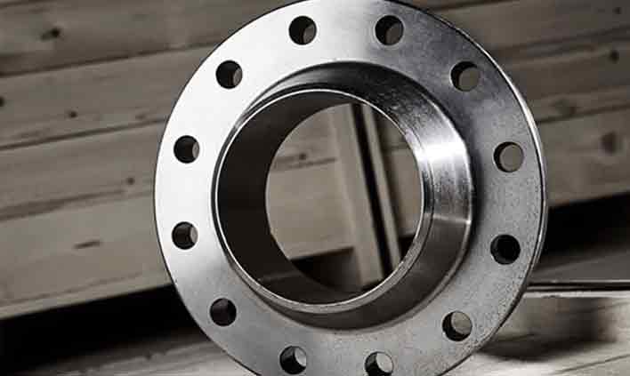
Tubewell Steel & Engg. Co. is a leading manufacturer and stockist specializing in Alloy Steel Pipes, Tubes, Fittings and Flanges for critical industrial applications.
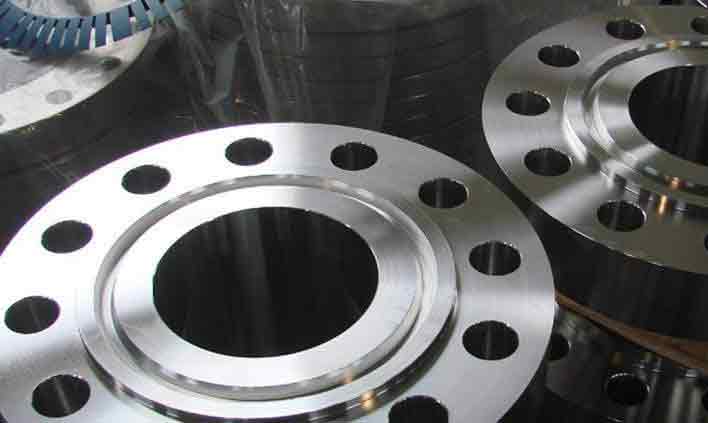
Modified 9Cr-1Mo-V forged flanges with exceptional creep strength for supercritical and ultra-supercritical power plant piping.
Tubewell Steel & Engg. Co. manufactures, stocks and supplies ASTM A182 F91 flanges from Mumbai, India. F91 is a creep strength-enhanced ferritic (CSEF) steel micro-alloyed with vanadium, niobium and nitrogen, offering roughly twice the allowable stress of F22 at 550–600°C – enabling thinner, lighter piping in supercritical power plants.
The creep strength-enhanced flange grade for modern high-efficiency plants
ASTM A182 F91 is a modified 9% chromium – 1% molybdenum steel with controlled additions of vanadium (0.18–0.25%), niobium (0.06–0.10%) and nitrogen (0.03–0.07%). After normalizing and tempering it forms a tempered martensitic structure strengthened by fine carbonitride precipitates, giving outstanding creep-rupture strength, good oxidation resistance and low thermal expansion. This allows designers to reduce wall thickness, weight and thermal-fatigue stresses compared with F22.
Because F91 performance depends on correct heat treatment, our flanges are normalized at 1040–1080°C and tempered at 730–800°C, with hardness verified on every piece and microstructure checks available. Flanges are CNC machined to ASME B16.5, B16.47, MSS SP-44 or EN 1092-1 with bores matched to the mating A335 P91 pipe. EN 10204 3.1 / 3.2 certification, IBR documentation and third-party inspection by TÜV, BV, SGS or Lloyd's can be provided.
Standard supply range for ASTM A182 F91 flanges
| Parameter | Details |
|---|---|
| Material Standard | ASTM A182, ASME SA182 |
| Grade | F91 (UNS K90901) |
| Dimension Standard | ASME B16.5 (1/2" – 24"), ASME B16.47 Series A & B (26" – 48"), MSS SP-44, EN 1092-1 |
| Size | 1/2" NB to 48" NB (DN 15 – DN 1200) |
| Pressure Class | ASME Class 150, 300, 600, 900, 1500, 2500 |
| PN Rating | PN6, PN10, PN16, PN25, PN40, PN64 |
| Flange Types | Weld Neck, Slip-On, Blind, Socket Weld, Threaded, RTJ, Long Weld Neck, Reducing, Orifice, Spectacle Blind |
| Facing | Raised Face (RF), Flat Face (FF), Ring Type Joint (RTJ), Tongue & Groove |
| Face Finish | Serrated 125 – 250 µin Ra (3.2 – 6.3 µm), smooth finish on request |
| Bore / Schedule | SCH 10 to SCH XXS, to match A335 P91 pipe |
| Heat Treatment | Normalized 1040 – 1080°C & Tempered 730 – 800°C |
| B16.5 Material Group | Group 1.15 (9Cr-1Mo-V) |
| Testing | PMI, Hardness, Tensile, Impact, UT, MPI / DPT, Microstructure, Visual & Dimensional |
| Certificates | EN 10204 3.1 / 3.2, IBR Certification, TPI Reports |
International equivalents of A182 F91
| Grade | ASTM / ASME | UNS | EN 10222-2 | W.Nr. | JIS G3203 | Nominal |
|---|---|---|---|---|---|---|
| F91 | A182 F91 / SA182 F91 | K90901 | X10CrMoVNb9-1 | 1.4903 | SFVAF28 | 9Cr-1Mo-V |
Equivalents are the nearest comparable grades for reference; confirm suitability against the governing design code before substitution.
Weight %, as per ASTM A182
| Element | C | Mn | P | S | Si | Ni | Cr | Mo |
|---|---|---|---|---|---|---|---|---|
| A182 F91 | 0.08 – 0.12 | 0.30 – 0.60 | 0.020 max | 0.010 max | 0.20 – 0.50 | 0.40 max | 8.0 – 9.5 | 0.85 – 1.05 |
| Element | V | Nb | N | Al | Ti | Zr | Remarks | |
| A182 F91 | 0.18 – 0.25 | 0.06 – 0.10 | 0.03 – 0.07 | 0.02 max | 0.01 max | 0.01 max | Fe balance | |
Minimum values at room temperature
| Grade | Tensile Strength | Yield Strength (0.2%) | Elongation (in 2") | Reduction of Area | Hardness (HBW) |
|---|---|---|---|---|---|
| A182 F91 | 620 MPa (90 ksi) min | 415 MPa (60 ksi) min | 20% min | 40% min | 248 max |
Typical values (for reference)
| Property | Metric | Imperial |
|---|---|---|
| Density | 7.76 g/cm³ | 0.280 lb/in³ |
| Melting Range | 1420 – 1500 °C | 2590 – 2730 °F |
| Modulus of Elasticity | 218 GPa | 31.6 × 10³ ksi |
| Thermal Conductivity (100°C) | 26 W/m·K | 15.0 BTU/h·ft·°F |
| Mean Thermal Expansion (20–300°C) | 11.3 µm/m·°C | 6.3 µin/in·°F |
| Specific Heat | 0.45 J/g·°C | 0.11 BTU/lb·°F |
| Max. Service Temperature | ≈ 650 °C | ≈ 1200 °F |
ASME B16.5 Class 150 & Class 300 flanges – dimensions in mm
| NPS | Cl.150 OD | Cl.150 Thk | Cl.150 BCD | Cl.150 Bolts | Cl.300 OD | Cl.300 Thk | Cl.300 BCD | Cl.300 Bolts | RF Dia |
|---|---|---|---|---|---|---|---|---|---|
| 1/2" | 90 | 9.6 | 60.3 | 4 × 1/2" | 95 | 12.7 | 66.7 | 4 × 1/2" | 34.9 |
| 3/4" | 100 | 11.2 | 69.9 | 4 × 1/2" | 115 | 14.3 | 82.6 | 4 × 5/8" | 42.9 |
| 1" | 110 | 12.7 | 79.4 | 4 × 1/2" | 125 | 15.9 | 88.9 | 4 × 5/8" | 50.8 |
| 1 1/4" | 115 | 14.3 | 88.9 | 4 × 1/2" | 135 | 17.5 | 98.4 | 4 × 5/8" | 63.5 |
| 1 1/2" | 125 | 15.9 | 98.4 | 4 × 1/2" | 155 | 19.1 | 114.3 | 4 × 3/4" | 73.0 |
| 2" | 150 | 17.5 | 120.7 | 4 × 5/8" | 165 | 20.7 | 127.0 | 8 × 5/8" | 92.1 |
| 2 1/2" | 180 | 20.7 | 139.7 | 4 × 5/8" | 190 | 23.9 | 149.2 | 8 × 3/4" | 104.8 |
| 3" | 190 | 22.3 | 152.4 | 4 × 5/8" | 210 | 27.0 | 168.3 | 8 × 3/4" | 127.0 |
| 4" | 230 | 22.3 | 190.5 | 8 × 5/8" | 255 | 30.2 | 200.0 | 8 × 3/4" | 157.2 |
| 5" | 255 | 22.3 | 215.9 | 8 × 3/4" | 280 | 33.4 | 235.0 | 8 × 3/4" | 185.7 |
| 6" | 280 | 23.9 | 241.3 | 8 × 3/4" | 320 | 35.0 | 269.9 | 12 × 3/4" | 215.9 |
| 8" | 345 | 27.0 | 298.5 | 8 × 3/4" | 380 | 39.7 | 330.2 | 12 × 7/8" | 269.9 |
| 10" | 405 | 28.6 | 362.0 | 12 × 7/8" | 445 | 46.1 | 387.4 | 16 × 1" | 323.8 |
| 12" | 485 | 30.2 | 431.8 | 12 × 7/8" | 520 | 49.3 | 450.8 | 16 × 1 1/8" | 381.0 |
| 14" | 535 | 33.4 | 476.3 | 12 × 1" | 585 | 52.4 | 514.4 | 20 × 1 1/8" | 412.8 |
| 16" | 595 | 35.0 | 539.8 | 16 × 1" | 650 | 55.6 | 571.5 | 20 × 1 1/4" | 469.9 |
| 18" | 635 | 38.1 | 577.9 | 16 × 1 1/8" | 710 | 58.8 | 628.6 | 24 × 1 1/4" | 533.4 |
| 20" | 700 | 41.3 | 635.0 | 20 × 1 1/8" | 775 | 62.0 | 685.8 | 24 × 1 1/4" | 584.2 |
| 24" | 815 | 46.1 | 749.3 | 20 × 1 1/4" | 915 | 68.3 | 812.8 | 24 × 1 1/2" | 692.2 |
OD = Flange Outside Diameter, Thk = Minimum Flange Thickness (excluding 2 mm / 0.06" raised face), BCD = Bolt Circle Diameter, Bolts = No. × Bolt Diameter. All dimensions in mm unless noted.
Where ASTM A182 F91 flanges are used
Main steam and hot reheat lines in supercritical and USC units.
High-pressure superheater headers in combined-cycle plants.
Outlet headers, desuperheaters and attemperator connections.
Hydrocracker and heater piping needing creep strength at temperature.
Steam generator and secondary-side high-temperature piping.
Reformer and cracker transfer lines at elevated temperature.
Quality you can verify on every heat
Large inventory for fast dispatch
MTC EN 10204 3.1 / 3.2
Positive material identification
Pan-India & export shipping
Quick answers about A182 F91 flanges
Get competitive pricing, ready stock and complete documentation.